PointPillars note
这篇文章也经常在其他文章中被提到,该网络特点就是具有非常快的推理速度。这篇文章的一个出发点之一,就是不想使用速度较慢的 3D convolution。这篇笔记比较潦草,但目的是梳理清楚模型的框架和流程
Abstract
In this work we propose PointPillars, a novel encoder which utilizes PointNets to learn a representation of point clouds organized in vertical columns (pillars). While the encoded features can be used with any standard 2D convolutional detection architecture, we further propose a lean downstream network
Introduction
Recently SECOND improved the inference speed of VoxelNet but the 3D convolutions remain a bottleneck.
In this work we use a single stage method
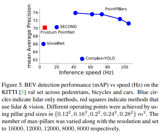
We show how all computations on pillars can be posed as dense 2D convolutions which enables inference at 62 Hz; a factor of 2-4 times faster than other methods
PointPillars Network
It consists of three main stages (Figure 2):
(1) A feature encoder network that converts a point cloud to a sparse pseudoimage;
(2) a 2D convolutional backbone to process the pseudo-image into high-level representation; and
(3) a detection head that detects and regresses 3D boxes.
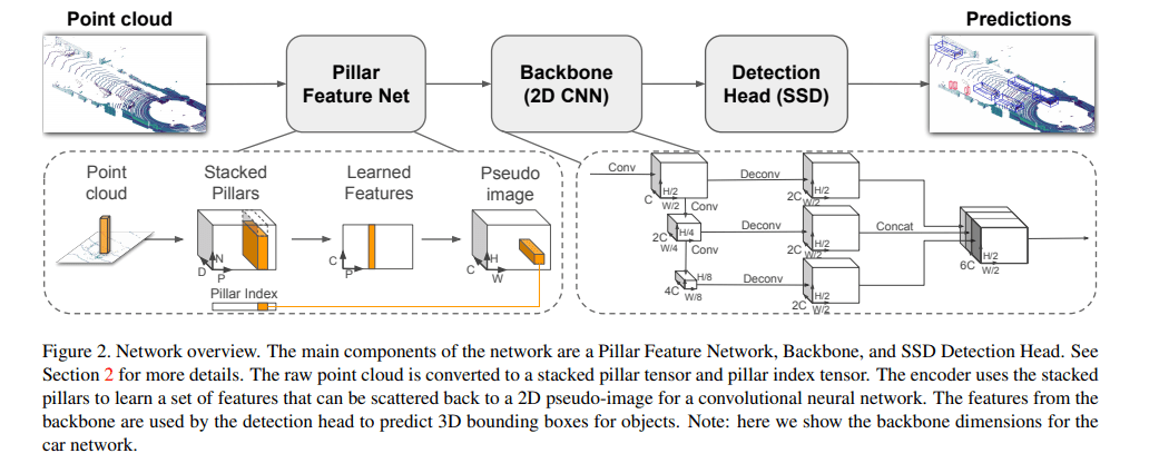
Pointcloud to Pseudo-Image
As a first step the point cloud is discretized into an evenly spaced grid in the x-y plane, creating a set of pillars P with |P| = B
The points in each pillar are then augmented with $x_c, y_c, z_c, x_p, y_p$ where the c subscript denotes distance to the arithmetic mean of all points in the pillar and the p subscript denotes the offset from the pillar x, y center.
The augmented lidar point l is now D = 9 dimensional $(x, y, z, r, x_c, y_c, z_c, x_p, y_p)$
The set of pillars will be mostly empty due to sparsity of the point cloud
为了更近一步处理 sparsity,规定了每个 sample,最多有 P 个 non-empty Pillars,每个 pillar 最多有 N 个 points,多于就进行随机采样。最终得到 tensor of size (D, P, N)。之后使用 PointNet,将每个 Pillar 进行 aggreagte 得到 feature tensor (C, P),再将这个 feature tensor 还原成为 feature map
Backbone
We use a similar backbone as VoxelNet and the structure is shown in Figure 2. The backbone has two sub-networks: one top-down network that produces features at increasingly small spatial resolution and a second network that performs upsampling and concatenation of the top-down features.
The top-down backbone can be characterized by a series of blocks Block(S, L, F). Each block operates at stride S (measured relative to the original input pseudo-image). A block has L 3x3 2D conv-layers with F output channels, each followed by BatchNorm and a ReLU
Detection Head
In this paper, we use the Single Shot Detector (SSD) [18] setup to perform 3D object detection. Similar to SSD, we match the priorboxes to the ground truth using 2D Intersection over Union (IoU)
Loss
Ground truth boxes and anchors are defined by $(x, y, z, w, l, h, \theta)$. The localization regression residuals between ground truth and anchors are defined by:
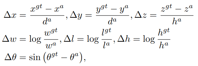
$d^a = \sqrt{(w^a)^2+(l^a)^2}$ ,the total localization loss is:

For the object classification loss, we use the focal loss [16]:

The total loss is therefore

Experiment
Params: Unless explicitly varied in an experimental study, we use an xy resolution: 0.16 m, max number of pillars (P): 12000, and max number of points per pillar (N): 100.
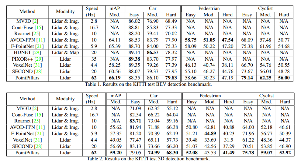
Speed v.s. resolution & presicion
